Overview
Need a Price for a standard Loadpin? Click here
Important: To order an SP Loadpin to a particular size and design visit our custom load cell page
The Straightpoint range of Loadpins (LMP’s) or shear pins are designed for use in applications where an end of line load cell cannot be used or when an integrated solution is required in applications such as pulley or sheave axles, moorings, supports, winches or support blocks.
Three versions standard loadpin are available:
- Long range 2.4GHz version providing industry leading wireless range of 1000m or 3280ft to SP's SW-HHP handheld or software options.
- Bluetooth output and can be connected to any smart phone running our free HHP app on iOS or Android at ranges up to 100m or 328ft.
- Cabled version with mV/V or analogue or digital output. Subsea option also available.
Often a customised design they are manufactured in-house from 17-4PH stainless steel and are normally supplied complete with an anti-rotation plate as a cabled or wireless solution.
Built to withstand the harshest environments in industries such as marine, offshore oil and gas or construction they are suitable for use in exposed situations and can be supplied as a subsea product with SubConn connectors to withstand immersion in seawater to extreme depths.
Straightpoint cabled Loadpins are typically connected to Straightpoint’s range of handheld displays or may be supplied with a vast array of output formats to include mV/V, RS-422, RS-485, utilising the ASCII, MODBUS TRU and CAN-BUS protocols or an analogue output such as 4-20mA for PLC integration.
Note: Please advise cable configuration on order - Radial or Axial Pin exit.
| Typical displacement of a loadpin under full load is around 0.04mm: |
Typical lifespan of a 1mv/v loadpin is in excess of 10 billion cycles: |
 |
 |
General Description
Standard Loadpin General Description
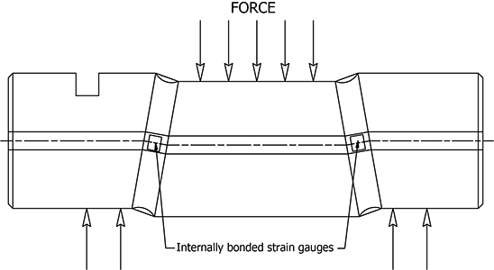
A loadpin senses the force applied across it, via strain gauges installed within a small bore through the centre of the pin. Two grooves are machined into the outer circumference of the pin to define the shear planes, which are located between the forces being measured.

Load Pin Environmental Protection
As the instrumented area of the load pin is totally contained within a small central bore, the load pin sensor is inherently waterproof. Manufactured from special stainless steels, fitted with welded or `O' ring sealed end caps and with special attention to the signal cable glanding, a very high operating reliability can be guaranteed even for load pins operating underwater.
Typical Locations
Loadpin Typical Locations
If a pin exists within a defined load path or can be fitted to experience a force, then a Straightpoint Load Pin can be installed to monitor that load. The sketches below show typical locations for load pins.

Specifications/Technical Data
|
|
|
|
 |
| |
|
Standard Loadpin specifications
|
| Part Number |
LP500KG |
LP1T |
LP2.5T |
LP3.5T |
LP6.5T |
LP15T |
LP25T |
LP50T |
LP100T |
LP250T |
LP500T |
LP750T |
LP1000T |
LP1500T |
| Capacity |
500kg |
1000kg |
2.5te |
3.5te |
6.5te |
15te |
25te |
50te |
100te |
250te |
500te |
750te |
1000te |
1500te |
| 1100lbs |
2200lbs |
5500lbs |
7700lbs |
14,000lbs |
33,000lbs |
55,000lbs |
110,000lbs |
220,000lbs |
550,000lbs |
110,0000lbs |
165,0000lbs |
220,0000lbs |
330,0000lbs |
| Resolution |
0.2kg |
0.5kg |
0.001te |
0.001te |
0.002te |
0.002te |
0.005te |
0.01te |
0.05te |
0.1te |
0.2te |
0.2te |
0.5te |
0.5te |
| 0.5lb |
1lb |
2lb |
2lb |
5lb |
5lb |
10lb |
20lb |
100lb |
200lb |
500lb |
500lb |
1000lb |
1000lb |
| Weight |
0.9kg |
1kg |
1.2kg |
1.4kg |
2kg |
3.1kg |
5.6kg |
8.6kg |
11.8kg |
29.8kg |
79.2kg |
146kg |
275kg |
389kg |
| 0.4lb |
0.5lb |
0.9lb |
1.3lb |
2.6lb |
5lb |
10.3lb |
18lb |
24lb |
64lb |
172lb |
319lb |
603lb |
854lb |
| Units |
kgs,tonnes |
| Protection |
IP67 (IP68 available as option) |
| Safety Factor |
300% of SWL |
| Operating Temperature |
-20 to +70 °C |
| -4 to 158˚F |
| Accuracy |
±1% full scale |
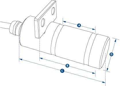
| Dim A |
24 |
35 |
45 |
50 |
63 |
75 |
89 |
102 |
110 |
130 |
225 |
295 |
360 |
430 |
| 0.94 |
1.38 |
1.77 |
1.97 |
2.48 |
2.95 |
3.50 |
4.02 |
4.33 |
5.12 |
8.86 |
11.61 |
14.17 |
16.93 |
| Dim B |
36 |
49 |
70 |
75 |
95 |
114 |
152 |
178 |
190 |
220 |
370 |
500 |
612 |
731 |
| 1.42 |
1.93 |
2.76 |
2.95 |
3.74 |
4.49 |
5.98 |
7.01 |
7.48 |
8.66 |
14.57 |
19.69 |
24.09 |
28.78 |
| Dim C |
70 |
80 |
100 |
105 |
125 |
150 |
195 |
225 |
230 |
300 |
440 |
590 |
712 |
832 |
| 2.76 |
3.15 |
3.94 |
4.13 |
4.92 |
5.91 |
7.68 |
8.86 |
9.06 |
11.81 |
17.32 |
23.23 |
28.03 |
32.76 |
| Dim ØD |
20 |
20 |
25 |
30 |
40 |
50 |
63 |
75 |
88 |
125 |
170 |
200 |
250 |
275 |
| 0.79 |
0.79 |
0.98 |
1.18 |
1.57 |
1.97 |
2.48 |
2.95 |
3.46 |
4.92 |
6.69 |
7.87 |
9.84 |
10.83 |
Example application
Loadpin used within Spelter and Wedge Sockets